Creating an animated 8x8 Led Matrix
TLDR
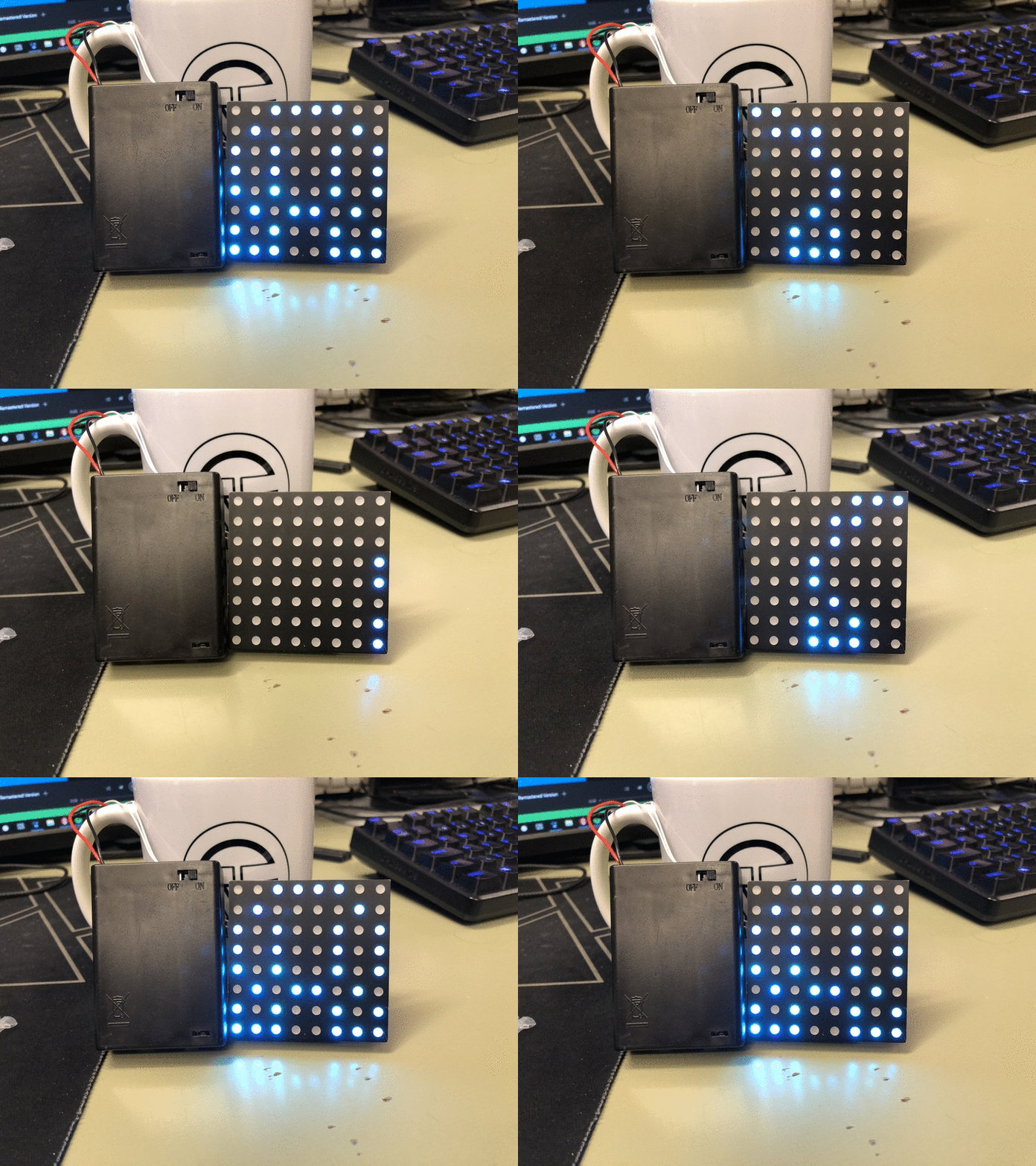
This is a 8x8 led matrix which uses a ATXMega64A4 to draw 8x8 bitmap image in RGB which can be sequenced into animations. All code and PCB design files are available at my GitHub Page.
Motivation
In the student organization Omega for people studying Electrical Engineering at NTNU there has been a long tradition with making led plates displaying the emblem of the organization. It is today made up of red LEDs which are shaped into an omega sign. This would be worn at formal ceremonies or social happenings organized by Omega and would serve as a party gimmick.
So naturally when I became a member I wanted to do something more and create something that could also improve my understanding of electronics. I decided to create a RGB led matrix instead which should have these criteria’s
Programmable
Modular
And ofc flashy
Design Phase
After some searching online I found premade 8x8 RGB matrix on eBay for about $3 USD, of course I could have made this myself but I decided to use my energy on the driver board. From there the design was based around the pins of the panel and confined within its dimensions.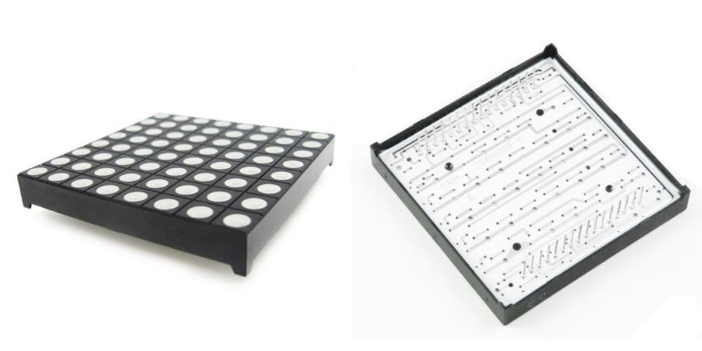
But to drive these I needed a way to switch the ground and power pins of the matrix on and off individually such that it was possible to control each led and colour separately according to its schematic.
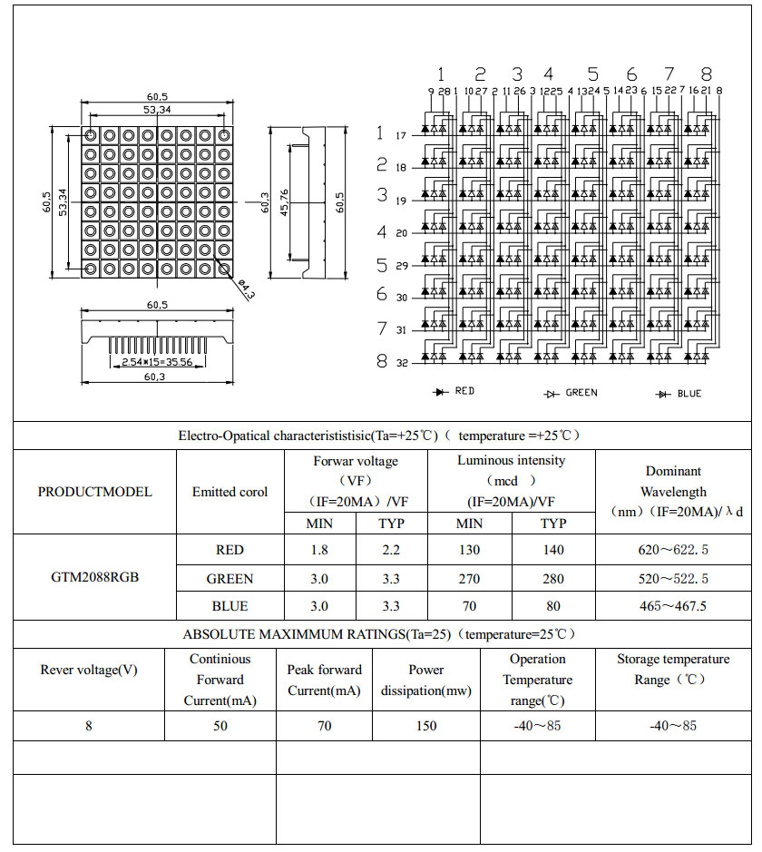
As the brain of the whole construction I decided to use a ATXMega64A4-AU not because it has any specs special features, I just had it handy. So most microcontrollers will work for the same purpose.
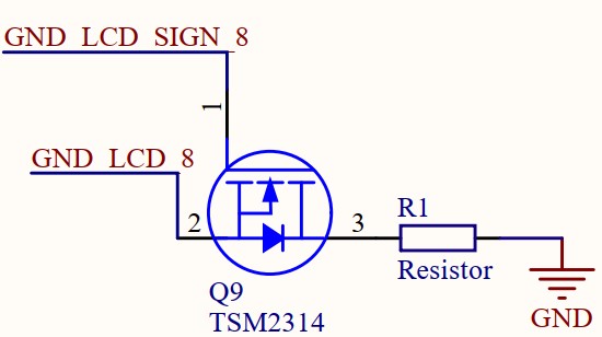
Pin switching (NMOS & PMOS transistors)
Since the digital signal coming from the microcontroller will be 3.3V there will be no problem switching an NMOS transistor on or off on the ground pins, since there will be no voltage drop from the source gate to ground.
Simply put the voltage on gate must be higher than the voltage drops from drain to ground. And also maintain a difference higher than the threshold voltage given in the datasheet.
$V_{ threshold }<(V_{gate}- V_{source})$
However, the $V_{cc}$ (power supply voltage) will not work with the same design as the voltage drop across the source pin will be higher due to the LEDs it is supplying resulting it not being able to switch. A solution to this is to use a PMOS and an NMOS transistor together and create something called a high side switch. This will use the $V_{cc}$ voltage to switch on the PMOS transistor and a NMOS transistor controlled by the microcontroller to pull this control signal down to ground to turn
the PMOS transistor off.
Designing the circuit
As mentioned before design files are available on my GitHub with the corresponding component values. We build on the concept to use NMOS transistors to pull our led matrix pins down to ground. And PMOS in combination with NMOS transistors todo high side switching.
A voltage regulator is used to takes the battery voltage down to 3V so we don’t fry the microcontroller.
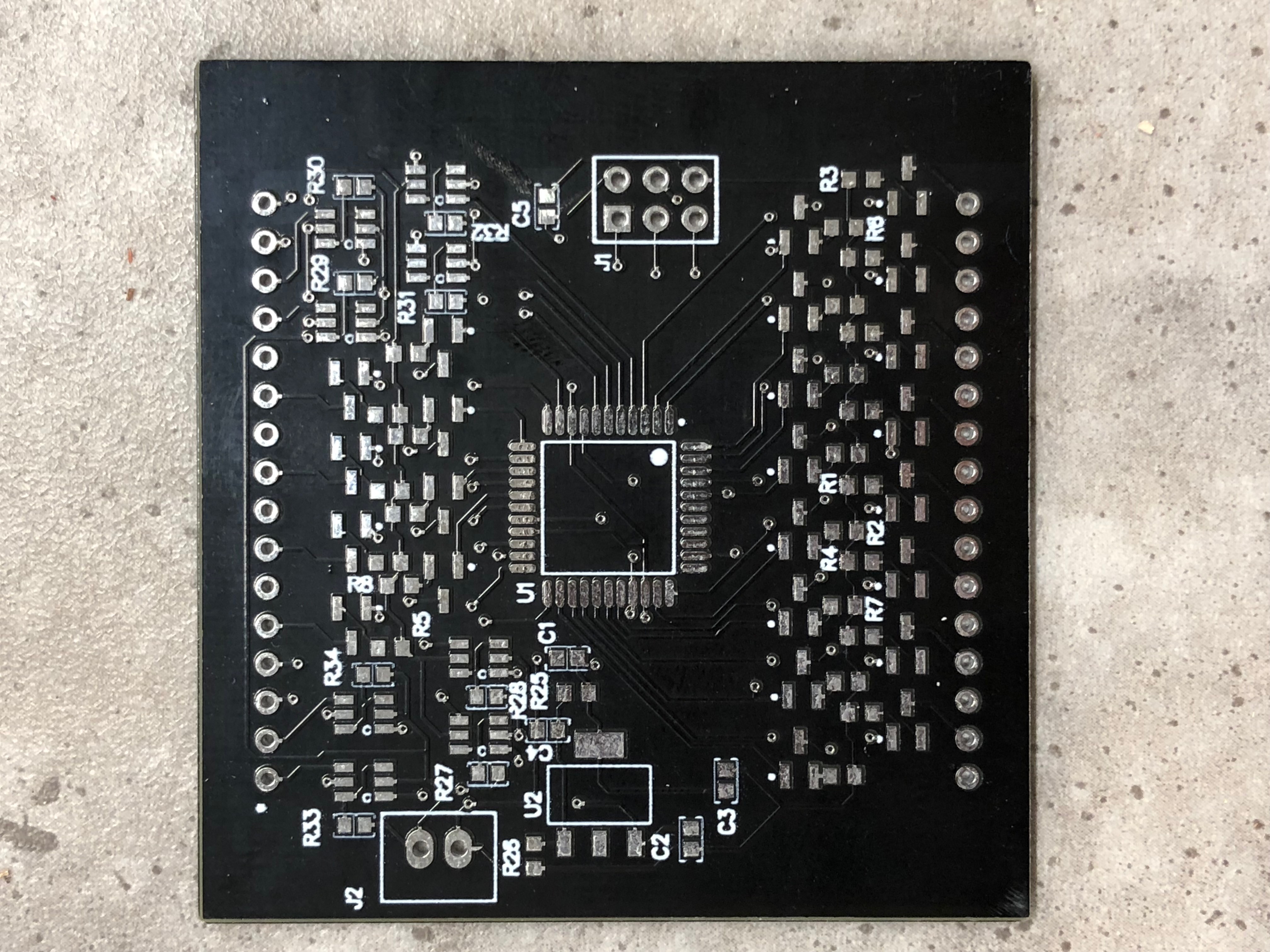
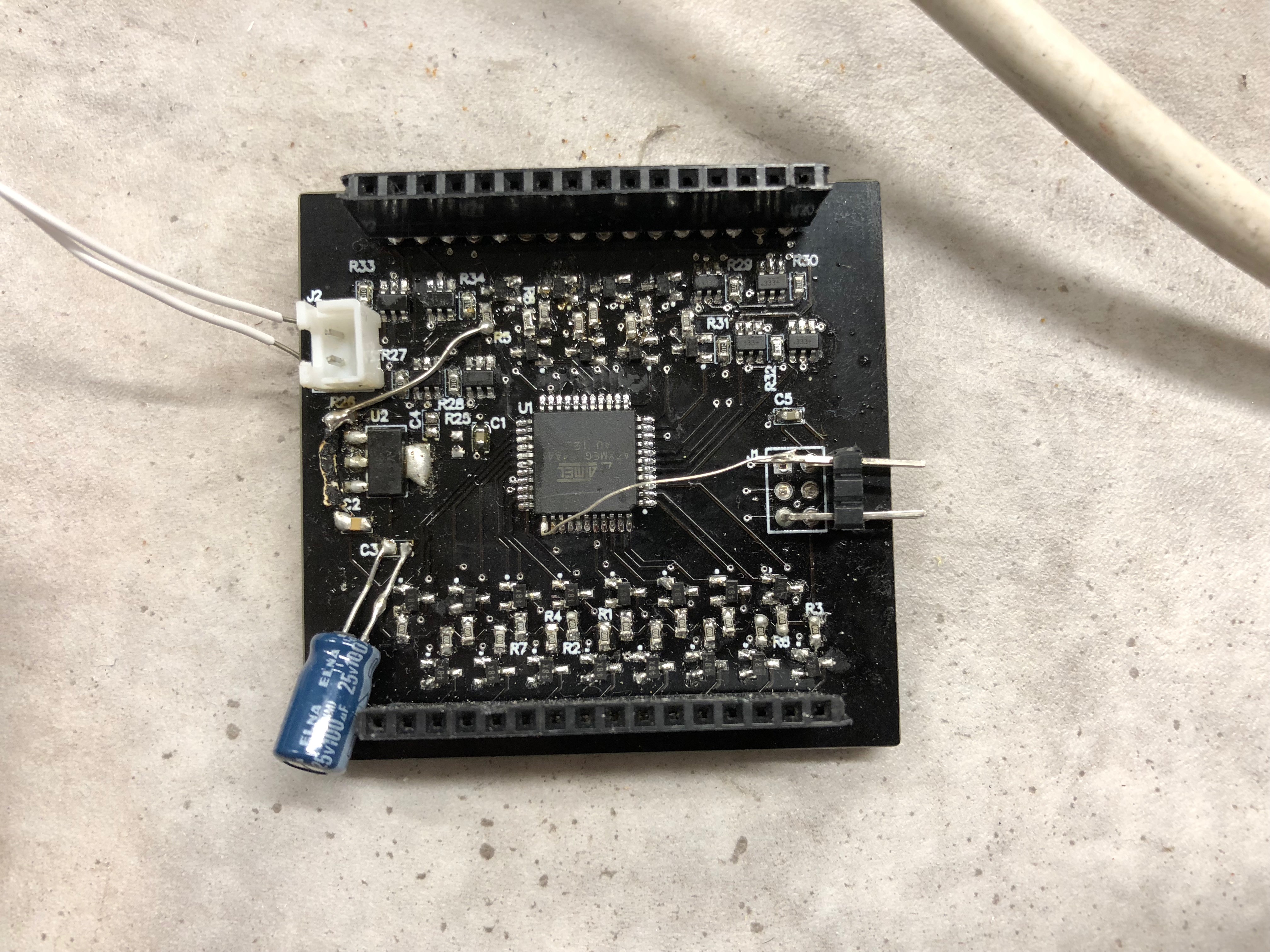
After drawing the circuit in Altium Designer and ordering the PCB from China we can finally begin assembling and programming the microcontroller
Software
For us to obtain the desired effect we need a way to control every pin connected to our transistors with a refresh rate that makes an animation. Pulse-Width Modulation (PWM) is a good way to control these pins, however the ATXMega64A4 does not have 32 PWM pins so we need to resort to something called software PWM. Rather then using dedicated hardware modules for switching on and off pins we use an internal timer on the microcontroller which counts to a certain value in a time based on the clock frequency of the microcontroller.
Now since we can switch on & off pins based on a time interval, we use this to draw one of the eight rows on the led matrix. The animation is retrieved from a 8x8 bit map array which contains each image to be displayed on the led matrix where each row on the bitmap is drawn every time our internal timer reaches it set limit.
You can find my microcontroller code with my design files on GitHub.
Thank you for reading my wall of text, and hope you found it interesting :)
– O.S.